Recently some users of the of DivMMC EnJOY! SD card interface had to return their interface because it got defective.
All of them used the Amstrad versions of the ZX Spectrum: the +2A / +2B or +3 model.
The specific thing about these models is that they use an external power supply with +5V, +12V and -12V.
As the ZX Spectrum was first produced in 1982, these machines are about 30 years old – the Amstrad versions are from 1986/1987, so about the same age.
By the way: the older ZX Spectrum models (made by Sinclair itself) had an internal voltage circuit which was fed by a 9V external transformer. These never gave any problem to a DivMMC EnJOY! interface.
It’s not that weird that power the corresponding power supplies (PSUs) will develop problems due to that age.
As I had 4 defective DivMMC EnJOY! interfaces within two months, all connected to a ZX Spectrum +2A/+2B/+3, my early conclusion was that these PSUs are now failing more and more.
But what is odd is that the machines themselves kept working, even after the DivMMC EnJOY! developed a defect.
So I had to prove that it is indeed the PSU is the troublemaker.
The first thing I did was develop a small PSU replacement using a modern switching 12V power supply, and a 12 to 5V DC-DC converter:
![13418482_1722048621388187_4275637026842171951_o[1]](https://www.bytedelight.com/wp-content/uploads/2016/09/13418482_1722048621388187_4275637026842171951_o1.jpg)
The -12V isn’t needed for normal operation of those machines, only when using the RS232 or MIDI output or the external ZX Keypad.
Almost noone use that (except for myself: I built a ZX Spectrum laserharp using the MIDI output of a ZX Spectrum +2B), so I left it out.
This power supply worked like a charm!
Some test users (both had a defective DivMMC EnJOY! twice, caused by the same machine) who I sent this replacement PSU for free didn’t have any problem anymore after using only that one.
But the question remained of how to prevent this problem with other ZX Spectrum +2A/+2B/+3 users.
The defect caused on the DivMMC EnJOY! was the voltage regulator and the CPLD chip.
This Xilinx CPLD is known to be very stable, so something like a voltage spike must have destroyed it.
My best guess was the voltage regulator (an XC6206P33) which had troubles with the old PSUs.
So a week ago I was looking for an alternative.
My first thought was to google for “XC6206P33 problems”, and indeed I found a German forum which described that this vreg is very sensitive to any voltage above 6V.
I had read that the maximum input voltage of this regulator is 6V, but I assumed that was the maximum continuous input voltage
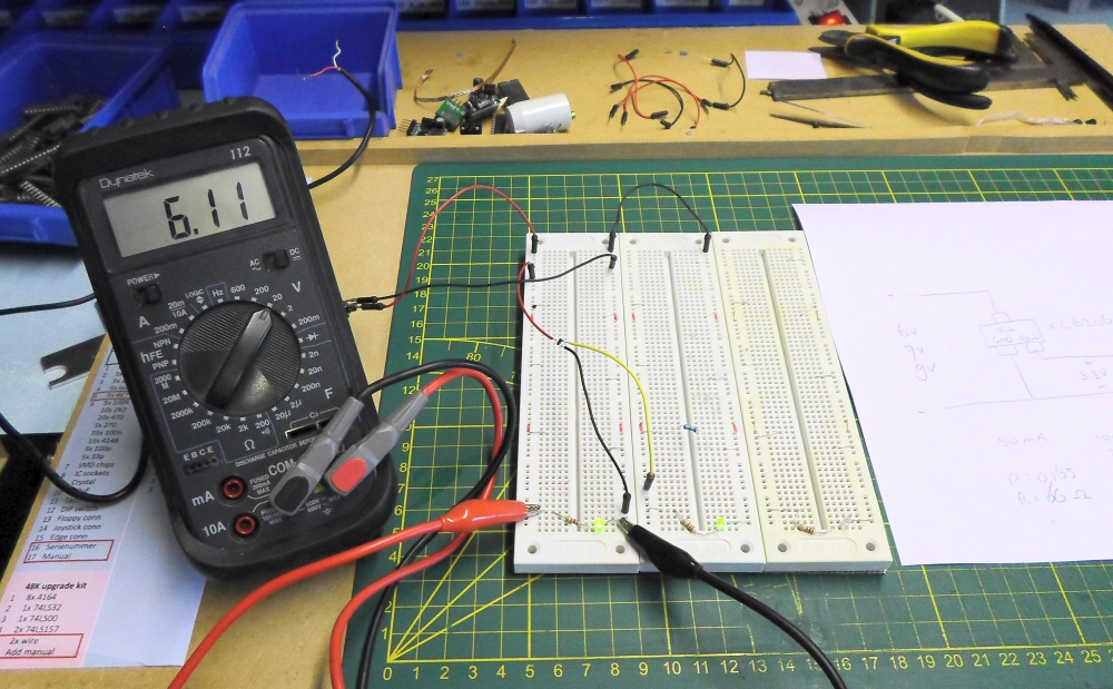
I needed to know it for myself, so I created a test setup:
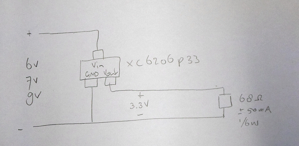
I wanted to know the output voltage with some load that represents the CPLD of the DivMMC EnJOY!, and with several input voltages above 5V.
Here’s the test setup without load and 5V input.
I mostly show the input voltages on the photos so you know what I was using when taking them. but there are two leds on the board showing if input and output voltage are present.
I thought that once the XC6206P33 is destroyed, the output voltage will dissapear and the right of the two leds will go off.
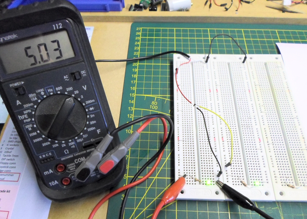
No load was attached when taking this picture.
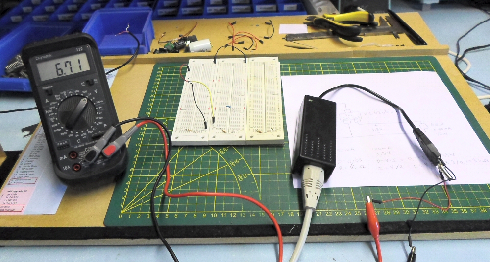
Next I attached a 6V power supply (I have them for old retrocomputer tape players):
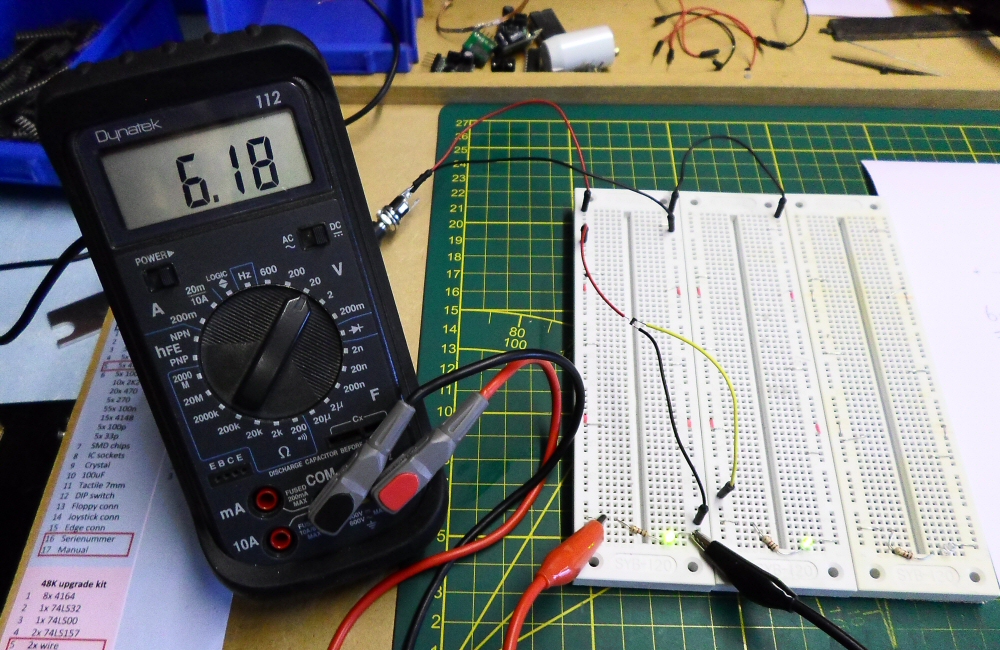
Then I added a load, which results in a current of about 50mA:
It still runs fine at about 50mA @6V (I measured the 3.3V output too, which was ok):
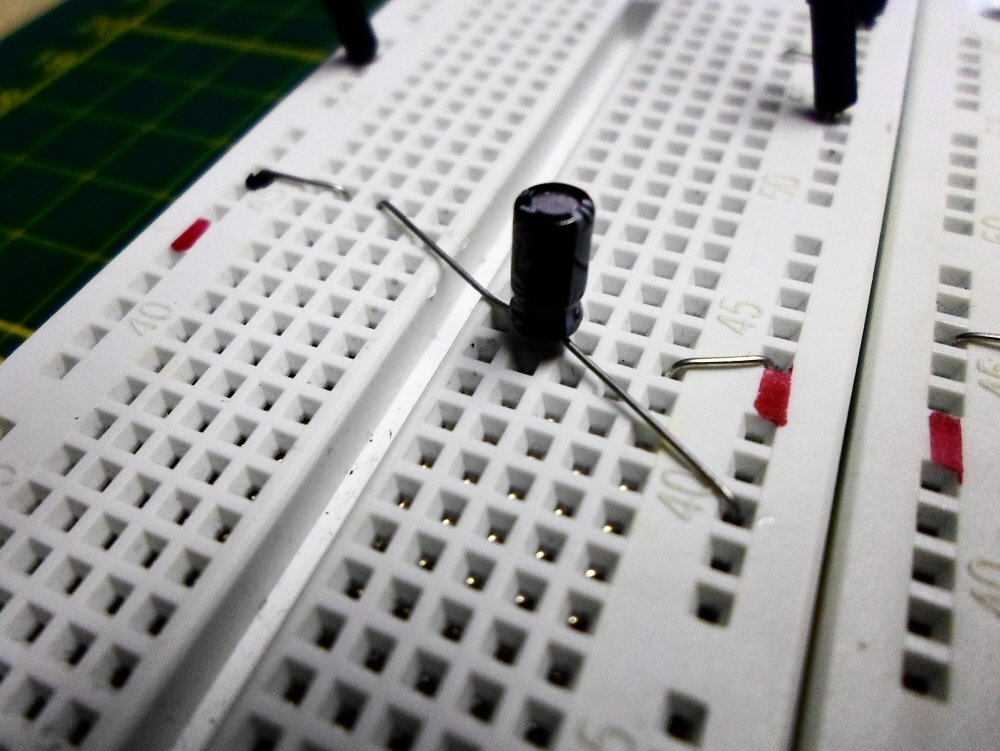
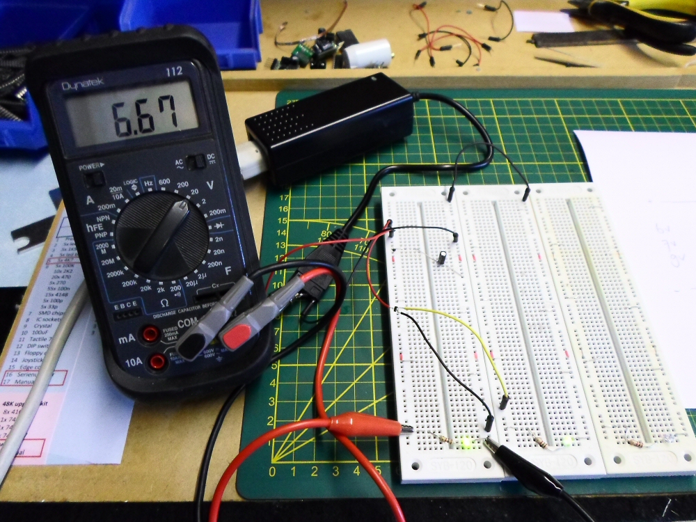
After that I got a 7V supply (using the difference between the 5V and 12V outputs of this switching PSU):
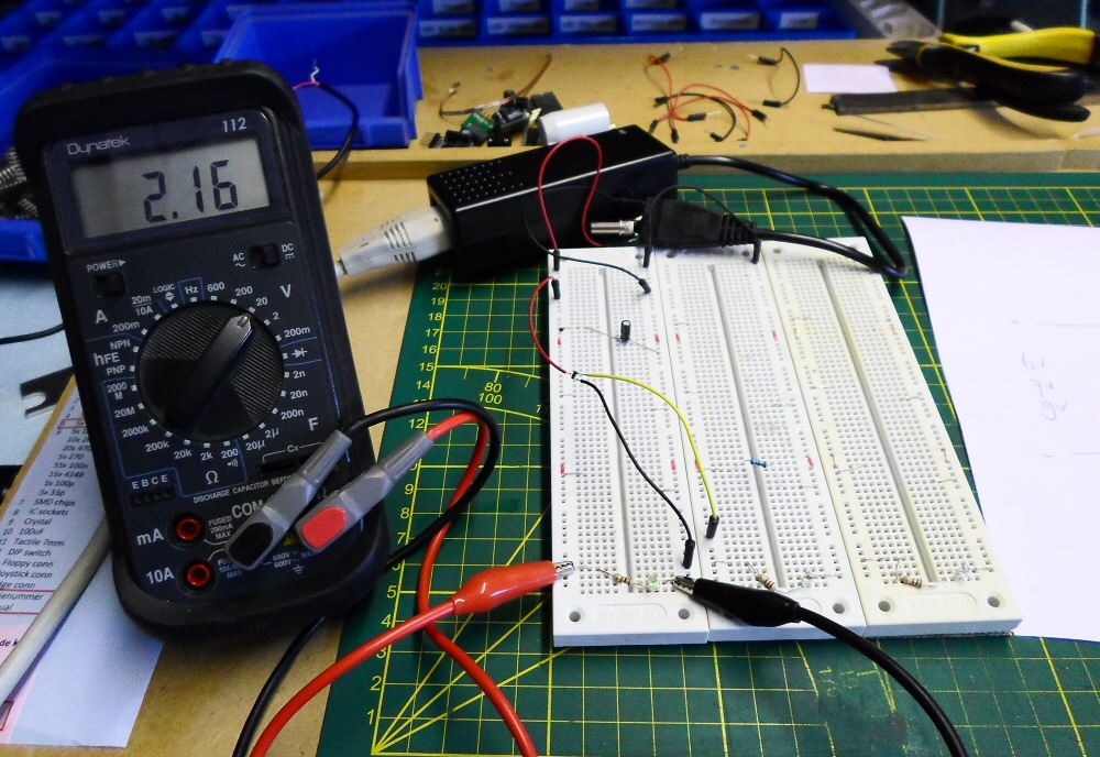
As these 5V +12V PSU outputs are not filtered much, I added a simple capacitor:
With the load the input (!) voltage of the XC6202P33 dropped to 2.16V!
I didn’t check the output this time (sorry!).
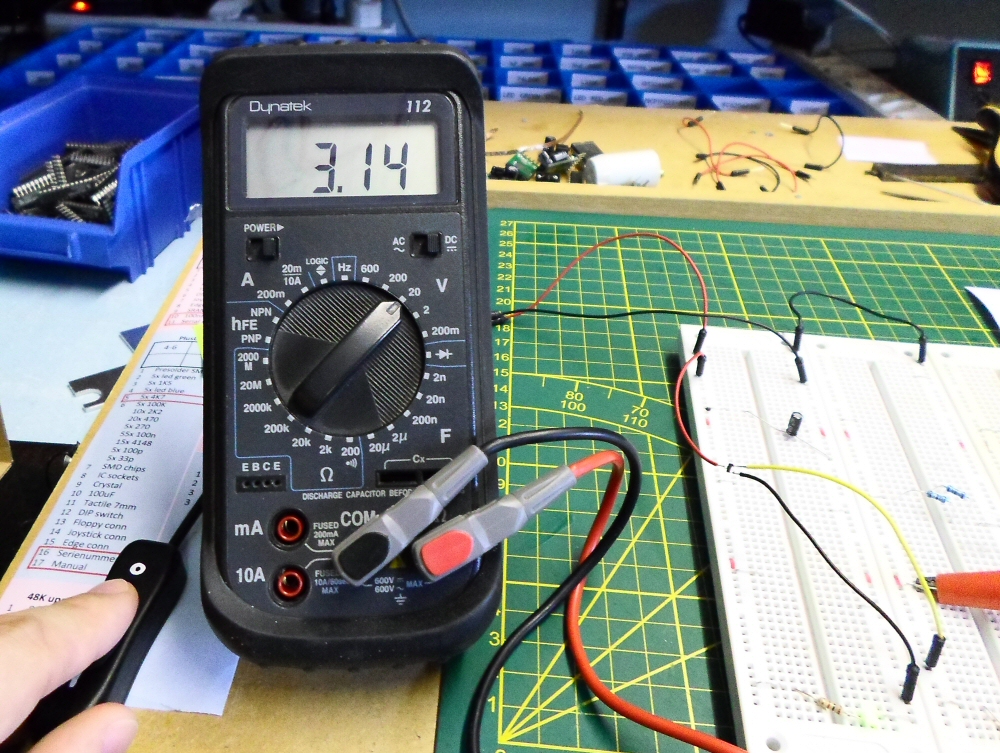
Strange thing was that without load, the XC6206P33 gave a neat 3.3V output (photo shows input voltage only, a little lower than 7V).
I got back to 5V to check if the XC6206P33 was still working ok, and it was.

Next was 9V.
Without load on the XC6206P33, it ran fine with an output still at 3.3V.
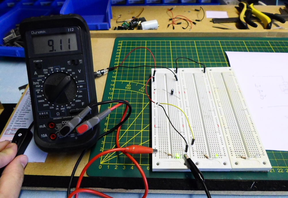
But putting back the resistor (50mA), and the input voltage dropped again, just as with the 7V PSU:

With some more load (100mA), the input voltage was 0.3V (!), so the input almost got short circuited!
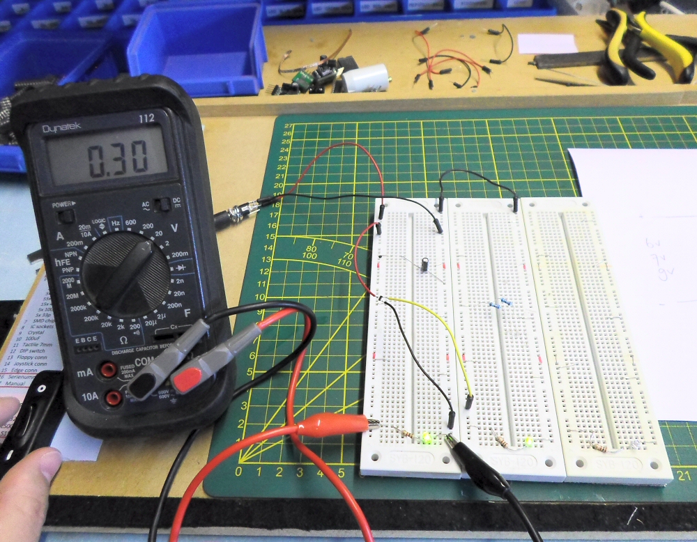
I was curious about the output.
It was way over 3.3V!
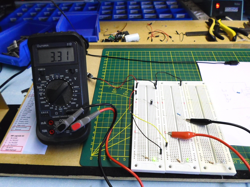
After a minute it dropped to less than 3.3V:
But the XC6206P33 still was working, although I expected it to collapse.
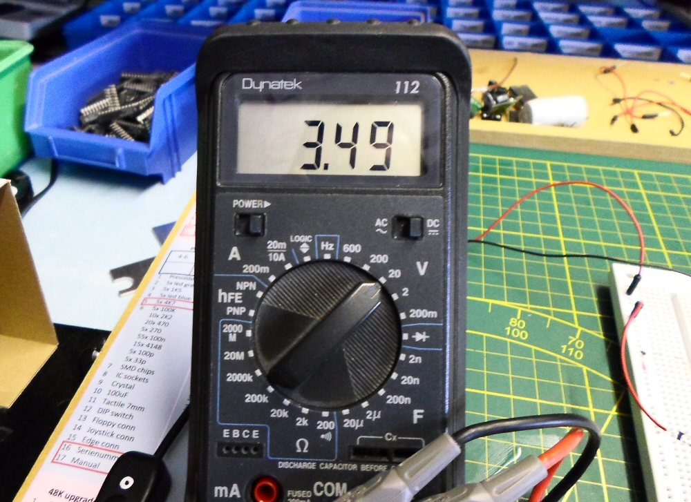
I thought I’d test one higher input voltage, 12V this time.
Here’s the output voltage:
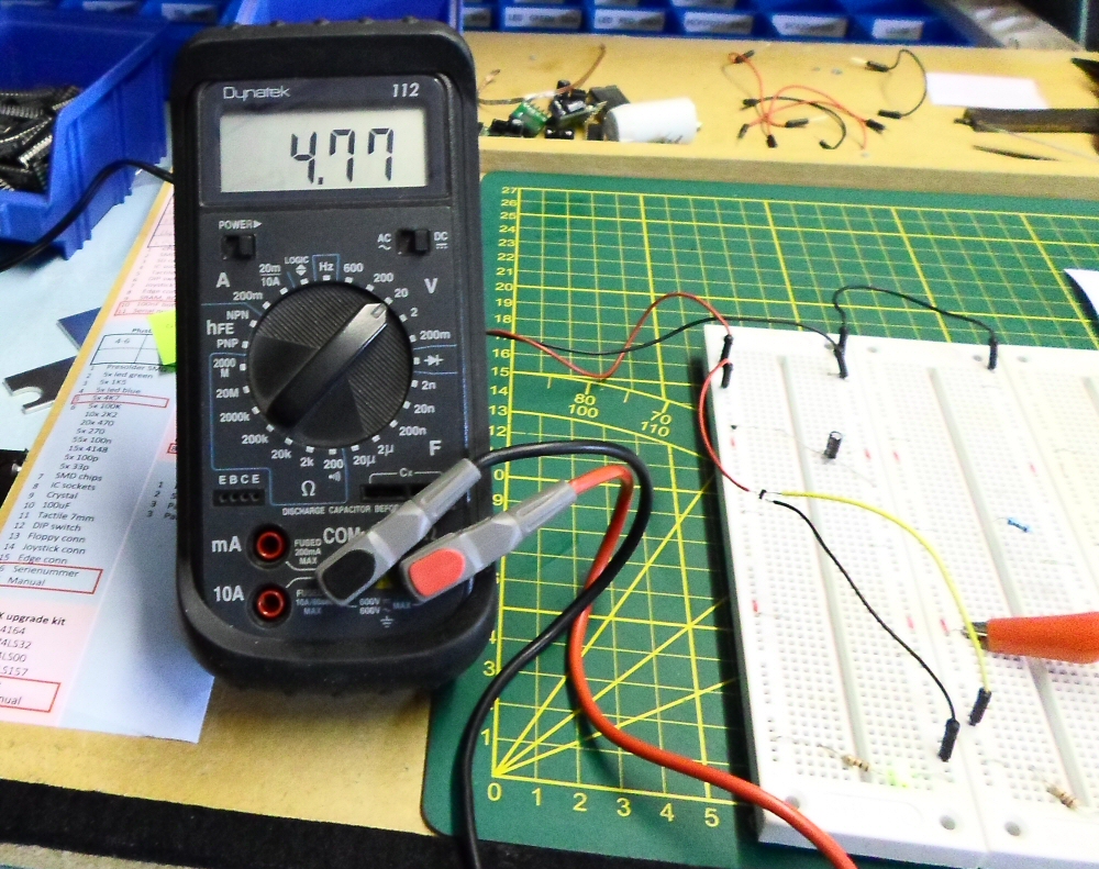
4.77V! This will definately destroy the CPLD.
Now think of what happens in a situation with a voltage spike over 7V (on the 5V line of the ZX Spectrum +2A / +2B / +3 PSU):
1. The vreg will output a higher voltage than the nominal 3.3V for a short time.
2. The CPLD will break
3. The defective CPLD pulls the vreg with it at the same time, causing both to be destroyed
So IMHO this proves that the old Amstrad PSUs that came with the ZX Spectrum +2A/+2B / +3 are causing these problems.
It’s only a matter of time before the ZX Spectrums themselves will get in trouble.
There is a real need to replace these old PSUs.
After studying the XC6206P33 I selected this drop in replacement part (SOT-23-3 case) for the DivMMC EnJOY!: the MCP1702T-3302.
This voltage regulator has exactly the same environmental specs (same external capacitors, same footprint, etc), but can take up to 14.5V input voltage.
So I ordered some and put the MCP1702T-3302 to the test, with 12V input.
Here’s the output with 50mA load:
So from now I will use this MCP1702T-3302 voltage regulator on the DivMMC EnJOY!.
Of course I will repair defective ones that may occur in the future, but I will also motivate people to replace their PSU on the ZX Spectrum +2A / +2B / +3.
Ben
![]()