Took some time but here it is!
This is part 1, more to follow this week.
Why aren’t many ZX Spectrum interfaces compatible?
“Can I use a Spectranet and DivMMC together?”
“Can I use the PlusDlite and the ZX Spectrum +3 disk drive at the same time?”
I get questions like these a lot!
And yes, they are totally valid questions.
So let’s finally put the anwser in this post, will try to keep it in a nutshell!
ZX Spectrum architecture
The ZX Spectrum was developed to be an affordable machine back in the days.
One way of making that possible was by leaving out many components that other much more expensive systems had.
If you add external hardware to the ZX Spectrum, it’s usually accessed by I/O (input/output) ports.
The proper way of designing external hardware would be by ‘decoding its address bus’ using ALL 16 address lines from the ZX Spectrum.
However Sinclair themselves (the development team of the ZX Spectrum itself) already made an exception of this by claiming one address line for ULA (that big chip) purposes.
So it wasn’t already possible anymore to do proper address decoding.
And the way Sinclair did it, became kind of a standard with many hardware add-ons.
Many producers used just one or two address lines to decode for their hardware.
Doing it that way resulted in many devices becoming incompatible, especially more complex devices like Floppy Disk interfaces and these days the SD storage interfaces and now the Spectranet ethernet interface.
As a comparison: at the time when the ZX Spectrum was sold, many other machines had several expansion slots, but interfaces developed for those had more complete ‘address decoders’ to avoid conflicts.
Hence though those machines and add-ons were a lot more expensive.
So what about interfaces on the ZX Spectrum then?
The basic rule is: every two interfaces with ROMs and NMI circuits will collide by default.
All storage interfaces have at least their own ROM, and many have an NMI circuit.
Now some interfaces like Disciple have an inhibit switch that adds some kind of compatibility, but not much.
And there is no magic / standard way of working around this.
One ‘very difficult’ solution (it IS possible) is disabling the ROM and NMI on one interface but leaving it’s hardware available, so it can be accessed by commands from the other interface.
For example someone could write %-commands on Spectranet to add support to the +3 disk drive or DivMMC SD card and so on.
But there is another catch: with complex interfaces like Spectranet, DivMMC and others, there are often I/O conflicts as well.
That means that when the software tries to access the hardware on one interface, it accidentally may activate hardware on the other device.
To solve that, one of the interfaces needs to be changed on a hardware level.
Hence I keep saying: there is almost no way of doing this.
So you have to pick the setup you like the most.
Or two setups, or three… Mancave anyone??
ESXDOS 0.8.7 is out! With a bugfix for the ‘.MKDIR’ command
A new version of ESXDOS, version 0.8.7, has been released.
Amongst the changes is a bugfix for the ‘.MKDIR’ command that created nested folders that didn’t work.
Here’s the announcement and place where you can download this new ESXDOS release: http://board.esxdos.org/viewtopic.php?pid=1240#p1240
And here’s an upgrade instructions page: https://www.bytedelight.com/?p=140.
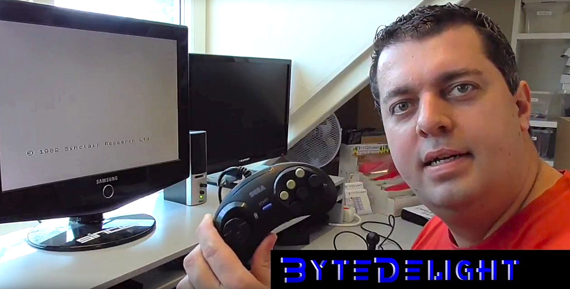
Sega gamepad (replica) tested on ZX Spectrum joystick interfaces
The remark at the end of the video about potentially shorting 5V to ground does not apply: the gamepad works well on all interfaces I tested, including DivMMC EnJOY! interfaces with integrated joystick port that have 5V on joystick pin 7.
Sam Coupe drive capacitors
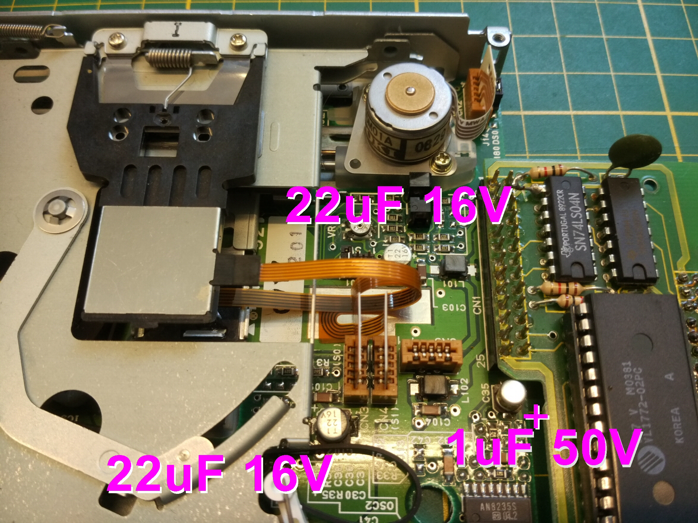
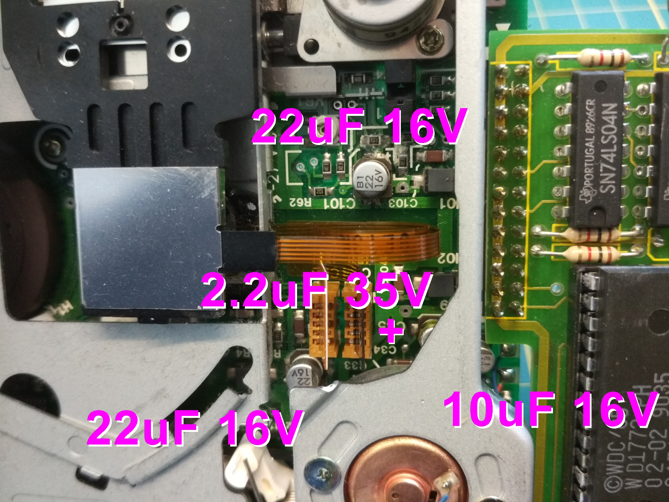
I’ve made some photos with details of the SMD capacitors used on the Sam Coupe disk drives.
I hope to be able to add the package specifications as well.
I’ve seen two revisions of the circuit boards inside the drives.
One has 3 capacitors and the other four, hence here you have 2 photos with the specs.
And underneath the photos you will find part numbers at Farnell or Mouser (not tested myself yet when writing this post, parts are on their way).
Farnell part numbers:
22uF 16V 5mm – Farnell: 2611359
1uF 50V 4mm BIPOLAR! – Mouser: 647-UWP1H010MCL
2.2uF 35V 4mm BIPOLAR! – Farnell: 2326177 / Mouser: 667-EEE-1VA2R2NR
10uF 16V 4mm – Farnell: 2901318
My thoughts on FPGA based ZX Spectrum clones
I would like to share my thoughts about FPGA clones of ZX Spectrums.
I was discussing this with some people during the last weeks, and thought to gather the things I wrote and make them public.
First, I really do like the developments that are going on, like the the ZX Spectrum Next, the ZX UNO and its XL brother the ZX GO, and more FPGA implementations.
But even though both the Next and the ZX-GO have some kind of an edge connector, to be honest I don’t think they are what the majority of enthusiasts are looking for.
Please read that again carefully: I say ‘majority of people’ since there its definitely interest in improvements like the Next, but machines with specific new features IMHO actually create new communities with ZX Spectrum roots.
I do want a complete Next myself 😉
But getting to what I call ‘purely ZX Spectrum FPGA based clones’..
(And again: this is what I think, and with some details I might be wrong or misinformed)
I think there will be interest in a ‘fully ZX Spectrum compatible’ FPGA-based board, when it:
1. Can be used with no hassle
2. Has a completely hardware add-on compatible edge connector
3. Are really affordable
Let me explain.
1. No hassle, just plug and play
When it comes to starting to use an FPGA clone, it’s often or maybe in al cases not as simple as one would like I think:
- A problem with many FPGA based clones at this moment is that they’re most often not as intuitive to use as an original ZX Spectrum: power on, get to BASIC and do what you want.
- Also documentation is IMHO far from available or ready, which makes it users hard to use it simply as a ZX Spectrum.
- Then I don’t like boot-delays because the system needs to go through a more general startup-procedure.
Then none of the current implementations as far as I know fit in an unmodified rubber-key case.
You only can easily obtain replicas of rubber-key cases, the other cases are harder to get but if you want to use an original case, the rubber-key one is the easiest choice.
So I think a clone should have just composite at RF, tape in and out at EAR and stereo sound at MIC (like the Harlequin 128) and DC in with an integrated bridge rectifier for safety and PSU compatibility.
I think there would be a LOT of interest in a ‘drop-in replacement’ board.
2. Hardware compatibility
When I was testing the edge connnector of the Next with several add-on, I couldn’t get it working.
The assistance I got during a live stream gave me the feeling that the team not yet put in much effort to test this themselves.
Which also gives me the feeling it doesn’t have much priority, and I wonder it’s actually possible to make it work completely: my experience with the development of the ZX-HD is that if it needs to do a lot on hardware level, a SOC or FPGA has its limitations.
Now with the UNO both the original version and the ZX-GO variant do not get a compatible edge connector.
I personally don’t like a breakout-box like required on the ZX-GO to make it possible to connect add-ons.
I think I’ve seen one other FPGA based clone with edge connector, but I think it was using a separate Z80 and many more parts, so it wasn’t as integrated as the ZX UNO and Next.
When it comes to the emulation: of course it should be accurate, but I have no doubt that is at a high level at this moment.
Though I do wonder how hard it will be to integrate full hardware I/O compatibility on the edge connector.
And that’s where I think a major problem lies: FPGA developers tend to spend a lot of time pushing as many features into the core as possible, and maybe only later start to think of hardware compatibility when it’s requested to use their FPGA implementation on a ZX Spectrum compatible board.
I think many cores started as ‘software emulation with original ZX Spectrum keyboard inputs’..
3. Affordability
I think a FPGA based clone board should be available for under a £100, maybe even less, something like £75.
The reason I say £75 is that since it can be done with only an FPGA and some minor and very cheap discrete parts, the board should cost less than a Harlequin kit, JS128 or something else.
But I know the cost price of one FPGA alone can be around £50, but maybe I’m mistaken.
My conclusions for now then
I think it’s time for someone (or a team) to create a, let’s say, an FPGA based toastrack clone, that fits in a rubber case without the need of customizing the case.
For about £75, which means parts should be £30 or less to make any profit (really, I know).
If anything should be added – like an SD card slot with logic inside the FPGA core, or RGB, VGA, HDMI or anything else, there should be a lot of thought put in of how to add those without needing to modify the case.
If that can’t be done, I’d say: put the additional features in an external interface.
But people should be able to use existing add-ons as well.
Talking about a ‘it can do all’ interface: I’m really curious about the DivGMX which seems to combine things like HDMI with sound over HDMI, DivMMC, TurboSound and much more on an ordinary ZX Spectrum.
But.. I’m not sure if it actually ‘uses’ the connected ZX Spectrum and acts like an interface, or that it ONLY uses the ZX Spectrum ‘as a keyboard’.
There should be one on its way for me to test soon.
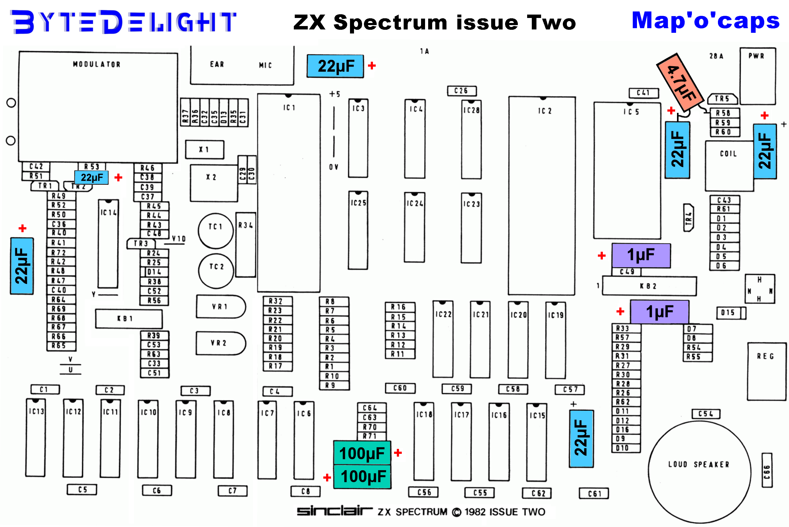
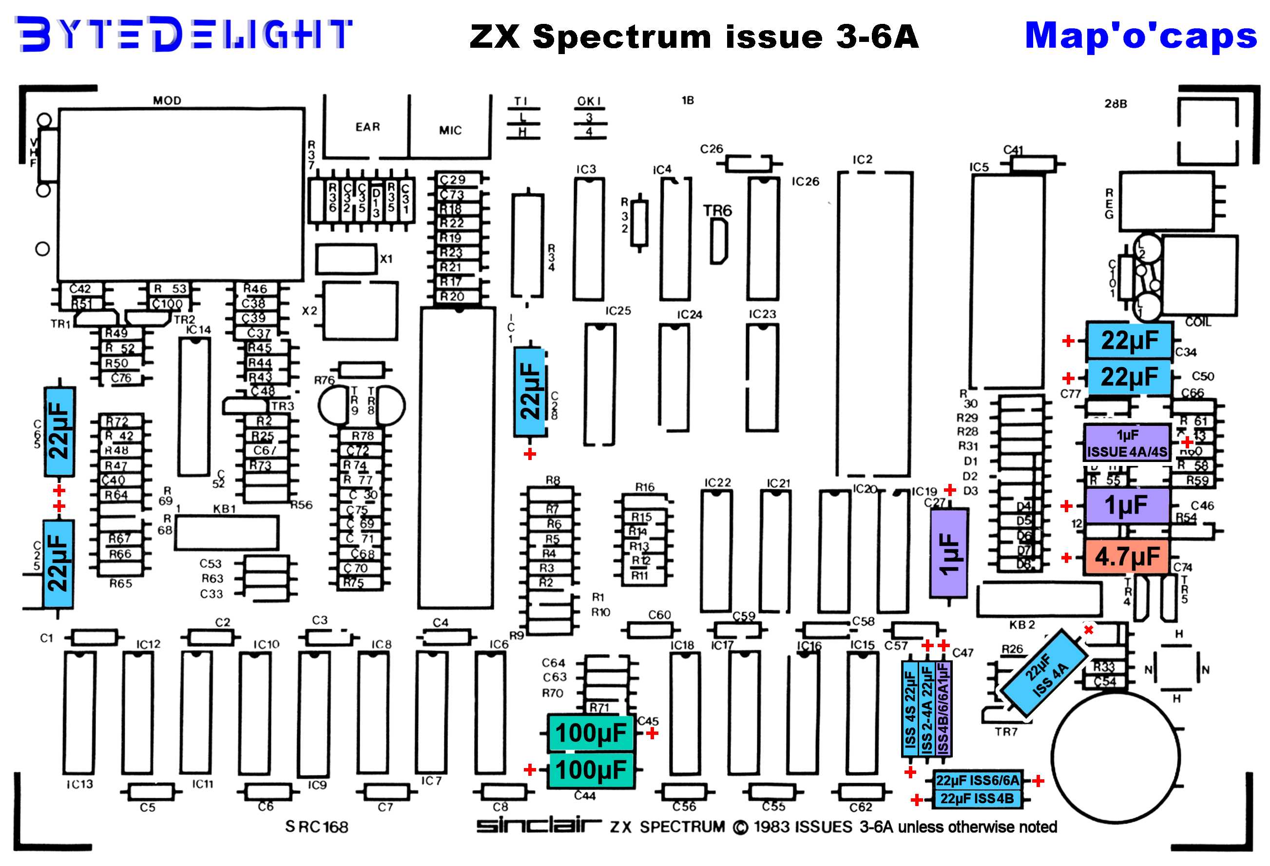
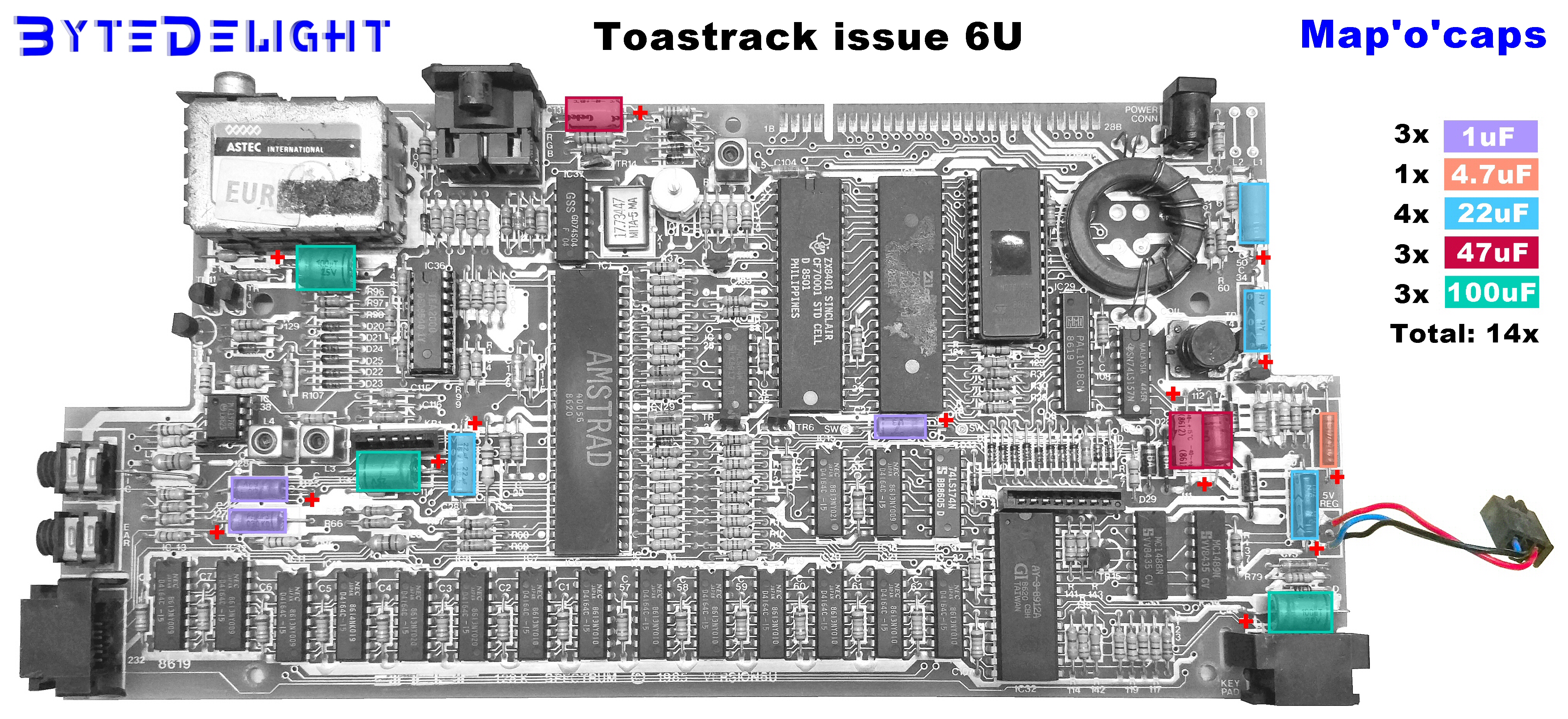
ZX Spectrum 16/48/128K capacitor maps
Get a MB02 for free!
‘It’s real’ they said:

Yes, RealSpectrum is one of the best ZX Spectrum emulators out there, though some of its features only work on a older machine with a 16 or 32 bit version of Windows98/XP.
But, it made it possible to get to use the MB02 interface for free!
Using a ZX Spectrum 48K ROM on a Harlequin 128
If you want to build and use a Harlequin 128 kit, but can’t find a ZX Spectrum 128K ROM (such as the Toast Rack one), you can just use a ZX Spectrum 48K ROM instead.
This will run any game without any problem, as shown in this video: https://www.youtube.com/watch?v=3g-s2ZOStOs.
48K ROMs are way more easy to obtain (though we sometimes offer a couple of original Toast Rack ROMs in the webshop).
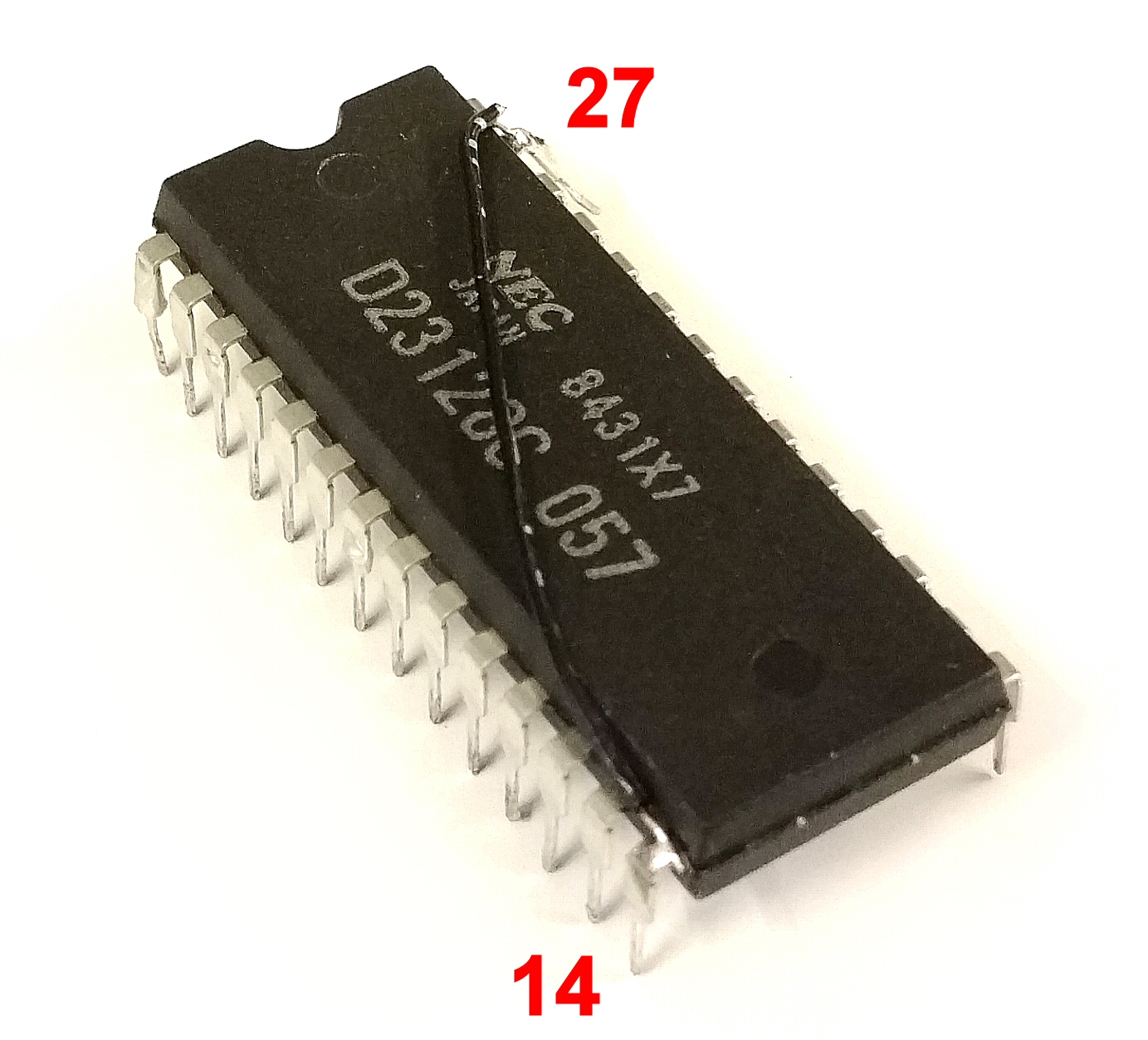
Underneath some photos of the small modification needed for using a 48K ROM in a Harlequin 128 board.
So you will need to solder a wire from pin 14 to pin 27, and bend pin 27 outside so it won’t go into the ROM socket on the Harlequin board:
Microdrive repair and maintanance guide
Also an older topic from me on WoS, but very useful.

